Seismic Performance Evaluation of a Large-Scale Composite MRF System with CFT Columns
Project Overview
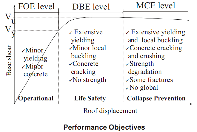
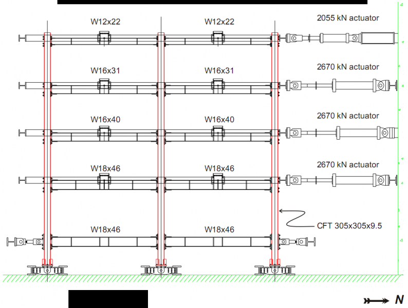
The seismic performance of a composite moment resisting frame (MRF) comprised of concrete filled tube (CFT) columns and wide flange beams was investigated experimentally. The four-story composite MRF test structure was designed using performance-based design concepts. The performance objectives include achieving: (1) the operational performance level under the frequent occurrence earthquake; (2) the life safety performance level under the design basis earthquake; and (3) the collapse prevention performance level under the maximum considered earthquake. The hybrid pseudodynamic test method was used to subject the test structure to these various seismic input levels. P-Δ effects associated with the gravity frames in the prototype building were included analytically in the tests. Results from the tests indicated that the structural performance under the simulated seismic loading was consistent with the expected performance for all three earthquake levels, indicating that effective seismic performance of composite MRFs with CFT columns can be achieved.
Test Matrix
| Test | Record | Earthquake Recording Station | Accelerogram Scale Factor | Earthquake Hazard Level | Test Method |
| FOE | 1979 Imperial Valley | Array 06 | 0.400 | FOE | PSD |
| DBE | 1994 Northridge | Canoga Park | 1.275 | DBE | PSD |
| MCE | 1994 Northridge | Canoga Park | 1.912 | MCE | PSD |
| DBE-A | 1994 Northridge | Canoga Park | 1.275 | DBE | PSD |
Summary
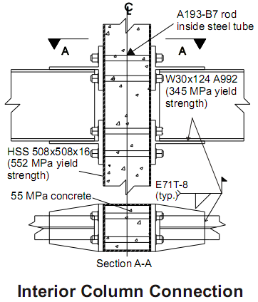
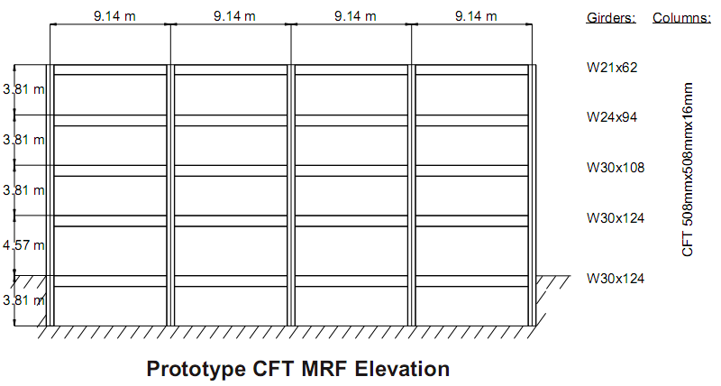
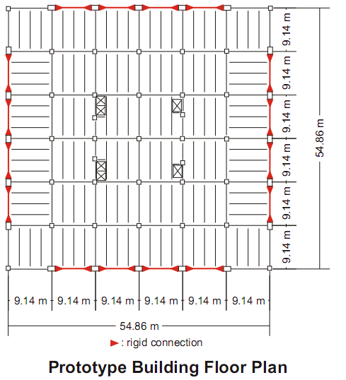
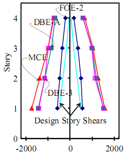
To investigate the seismic behavior of CFT-MRF systems, a 0.6 scale CFT-MRF test structure was developed from a prototype building designed using performance based design criteria, and was tested in the laboratory. The pseudodynamic hybrid test method was used to subject the test structure to several ground motions representative of three earthquake input levels, namely, the FOE, DBE, and MCE. The performance objectives for the structure included a fully operational condition under the FOE, and the life safety performance level and the collapse prevention performance level under the DBE and MCE, respectively. The IBC 2000 provisions were used to establish the required strength and stiffness of the structure. A weak beam-strong column configuration in the design was achieved using the AISC-LRFD criteria for the beam capacity and the ACI criteria for the CFT column capacity. Split tee beam-to-column moment connections were used to enable plastic hinges to form in the beams.
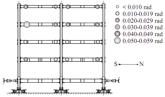
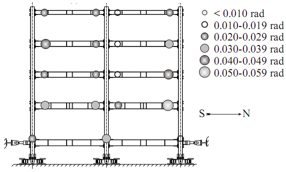
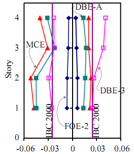
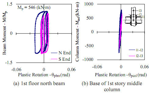
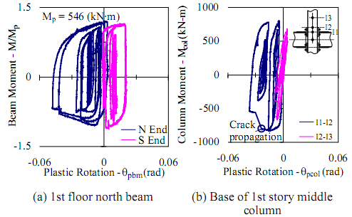
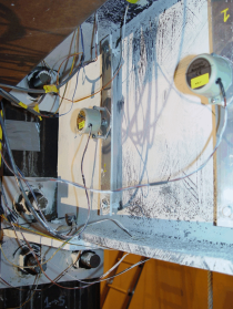
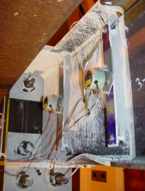
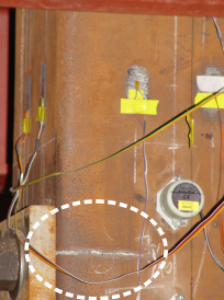
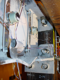
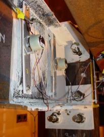
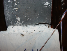
The test structure developed minor yielding during the FOE test. During the DBE test, the structure responded as a weak beam-strong column system, with extensive beam yielding and incipient beam local flange and web distortion at a few plastic hinge regions. The design drift limit of 2.5% was exceeded under the DBE, however, no strength degradation occurred. During the MCE test, extensive beam local buckling and yielding occurred in the beams, as well as yielding and concrete crushing at the base of the first story columns. In addition, the steel tube at the base of the first story center column fractured at the net section of the tube at the beam-to-column connection. This damage to the test structure during the MCE did not cause collapse, and stable, ductile behavior was observed. The test structure sustained a subsequent DBE level aftershock, thereby exceeding the requirements of the collapse prevention performance level.
The test structure response was consistent with the expected performance for all seismic input levels, indicating that effective seismic performance of composite MRFs with CFT columns can be achieved. The system overstrength during the DBE and MCE tests was 3.11 and 3.54, respectively, and was greater than the value of 3.0 for special MRFs in current seismic design provisions. Consequently, an overstrength factor value larger than 3.0 should be considered in design. The net section fracture at the ground floor level of a CFT column with a split tee beam-to-column connection can be avoided by reinforcing the net section such that the plastic hinge forms in the gross section of the column above the net section.
The experimental data from the test structure has enabled the verification of analytical models for CFT-MRF members and systems. Analytical models developed by the writers were shown to accurately predict the test structure response (Herrera 2005). These models were also utilized to analyze the prototype structure under numerous ground motions scaled to the DBE and MCE. Performance similar to that observed in the test structure was observed at these two earthquake input levels.
Link to Timelapsed Video Results
Photos: Setup
Photos: Results
Related Publications
- Herrera, R. (2005). “Seismic behavior of concrete filled tube column-wide flange beam frames.” Ph.D. thesis, Lehigh Univ., Bethlehem, Pa.
- Ricles, J. M., Peng, S. W., and Lu, L.-W. (2004). “Seismic behavior of composite concrete filled steel tube column-wide flange beam moment connections.” J. Struct. Eng., 130 (2), 223–232.
- Peng, S. W., Ricles, J. M., and Lu, L. W. (2001). “Seismic resistant connections for concrete filled column-to-WF beam MRFs.” Rep. No. 01-08, ATLSS Engineering Research Center, Lehigh Univ., Bethlehem, Pa.
- Varma, A., Ricles, J. M., Sause, R., and Lu, L. W. (2002). “Seismic behavior and modeling of high-strength composite concrete-filled steel tube (CFT) beam–columns.” J. Constr. Steel Res., 58, 725–758.
Participants
Graduate Research Assistant
- Ricardo Herrera
Faculty Advisors
- James Ricles
- Richard Sause
Sponsors
- National Science Foundation (NSF)
- Pennsylvania Infrastructure Technology Alliance(PITA), Pennsylvania Department of Community and Economic Development
- Pennsylvania D.C.E.D., Pennsylvania Department of Community and Economic Development
- Steel Tube Institute of North America
