Self-Centering Damage-Free Seismic-Resistant Steel Frame Systems (Concentrically-Braced Frame)
Objectives
The overall project objective is to investigate a family of innovative self-centering (SC) steel frame systems which will withstand without damage the currently accepted design basis earthquake (DBE) for buildings. This current project task is focusing on the design and experimental performance of a self-centering concentrically braced frame (SC-CBF). The SC-CBF test structure was designed using performance-based design criteria for immediate occupancy under a median-level DBE and collapse prevention under the Maximum Considered Earthquake (MCE). This expected performance will be assessed and the design criteria verified through hybrid-pseudo-dynamic experiments on a 0.6-scale 1-bay 4-story SC-CBF.
Earthquake Simulations
1. Introduction
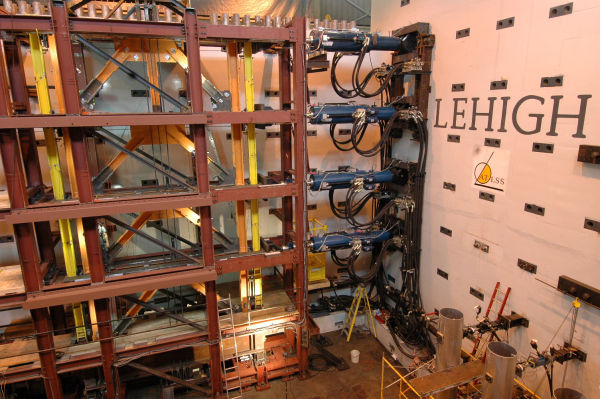
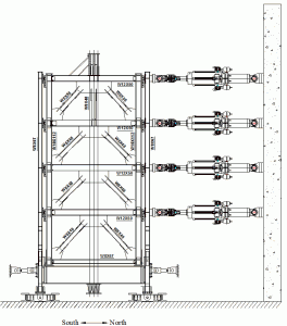
The SC-CBF configuration being tested is a one-bay four story concentrically braced frame with post-tensioning bars positioned in the middle of the frame and running vertically from a roof anchorage system down to a “basement” anchorage system. This setup is shown in Figure 1 and Figure 2. Other items of note in the test structure are that the floor system is supported by gravity columns that are adjacent to the rocking SC-CBF and that inertial forces are transferred from the floor system through the gravity columns to the SC-CBF through lateral load bearings. The lateral load bearings are shown in Figure 3. The SC-CBF structure being tested is designed using a performance-based design (PBD) approach for immediate occupancy (IO) under a median DBE and collapse prevention (CP) under a median MCE. These performance objectives are outlined graphically in Figure 4.
2. Experimental Program
The SC-CBF test frame was designed using the performance-based design (PBD) approach assuming that the SC-CBF is the lateral force resisting system for a 6×6-bay 4-story prototype building located on stiff soil (Site Class D (ASCE 7-05)) in Van Nuys, California. The 0.6 scale floor plan for this prototype building is shown in Figure 5. A total of eight SC-CBF frames would be in the building. One of these SC-CBF frames was tested in the laboratory while the gravity system of one-quarter of the building was modeled on the computer using a technique known as hybrid simulation. Preliminary stiffness tests of the frame were performed. Five DBE and five MCE scaled ground motion records, as well as one extreme MCE (xMCE) record, were used in the hybrid simulation. The hybrid simulation uses Rayleigh damping with 2% damping in the 1st mode and 5% in the 3rd mode. The explicit unconditionally stable CR integration algorithm is used to solve the equations of motion. Additional tests were performed at the frequently occurring earthquake (FOE) level and DBE level in fast hybrid simulations (near real-time load rates). The test matrices for the pseudo-dynamic tests and fast hybrid tests are shown in Table 1 and Table 2 respectively.
3. Related Publications
Roke, D.; Sause, R.; Ricles, J.M.; Seo, C.-Y.; and Lee, K.-S. (2006). “Self-Centering Seismic-Resistant Steel Concentrically-Braced Frames,” Proceedings of the 8th U.S. National Conference on Earthquake Engineering, EERI, San Francisco, April 18-22.
Sause, R., Ricles, J.M., Roke, D., Seo, C.-Y., and Lee, K.-S. (2006), “Design of Self-Centering Steel Concentrically Braced Frames,” 4th International Conference on Earthquake Engineering, Taipei, Taiwan.
4. Participants
Graduate Research Assistant
- David Roke
- Nathanial Gonner
- Brent Chancellor
Faculty Advisors
- Richard Sause
- James Ricles
Post-Doctoral Research Associates
- Choung-Yeol Seo
Table 1 – Hybrid Simulations
| Test Name | Input Level | Event | Station | Component | Scale Factor |
|---|---|---|---|---|---|
| DBE_5108-090_12-31-2009 | DBE | 1994 Northridge | Santasusana | 090 | 2.49 |
| DBE_cls000_12-31-2009 | DBE | 1989 Loma Prieta | Corralitos | 000 | 0.73 |
| DBE_h-shp270_B_12-31-2009 | DBE | 1979 Imperial Valley | Sahop Casa Flores | 270 | 1.75 |
| DBE_arl090_01-04-2010 | DBE | 1994 Northridge | Arleta | 090 | 1.40 |
| DBE_arl090_01-06-2010 | DBE | 1994 Northridge | Arleta | 090 | 1.40 |
| MCE_stn110_01-07-2010 | MCE | 1994 Northridge | LA – Saturn | 110 | 1.98 |
| MCE_a-tmz270_01-07-2010 | MCE | 1976 Friuli, Italy | Tolmezzo | 270 | 2.55 |
| MCE_lp-hda255_01-08-2010 | MCE | 1989 Loma Prieta | Hollister Diff Array | 255 | 2.24 |
| DBE_nr-pel360_01-08-2010 | DBE | 1994 Northridge | Hollywood Storage FF | 360 | 1.55 |
| MCE_cap000_01-11-2010 | MCE | 1989 Loma Prieta | Capitola | 000 | 1.45 |
| MCE_h-cpe237_01-13-2010 | MCE | 1979 Imperial Valley | Cerro Prieto | 237 | 3.85 |
| xMCE_tak090_01-13-2010 | MCE | 1995 Kobe, Japan | Takatori | 090 | 0.90 |
| MCE_lp-hda255_01-28-2010 | MCE | 1989 Loma Prieta | Hollister Diff Array | 255 | 2.24 |
| MCE_lp-hda255_02-02-2010 | MCE | 1989 Loma Prieta | Hollister Diff Array | 255 | 2.24 |
| xMCE_tak090_02-05-2010 | MCE | 1995 Kobe, Japan | Takatori | 090 | 0.90 |
| DBE_5108-090_A_02-09-2010_60pctPT | DBE | 1994 Northridge | Santasusana | 090 | 2.49 |
| DBE_5108-090_B_02-09-2010_0pctPT | DBE | 1994 Northridge | Santasusana | 090 | 2.49 |
Table 2 – Fast Hybrid Simulations
| Test Name | Input Level | Event | Station | Component | Scale Factor |
|---|---|---|---|---|---|
| FOE_b-krn270_B_02-03-2010_10x-2_RT | FOE | 1987 Superstition Hills | KRN | 270 | 1.08 |
| FOE_b-krn270_E_02-03-2010_4x-3_RT | FOE | 1987 Superstition Hills | KRN | 270 | 1.08 |
| DBE_cls000_A_02-03-2010_10x-1 (Ktfx2)_RT | DBE | 1989 Loma Prieta | Corralitos | 000 | 0.73 |
| DBE_cls000_B_02-03-2010_10x-2 (Ktfx3)_RT | DBE | 1989 Loma Prieta | Corralitos | 000 | 0.73 |
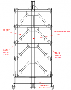
Figure 1 – Test Frame Setup
(a)
(b)
Figure 2: (a) Test frame in the laboratory; (b) schematic of test setup
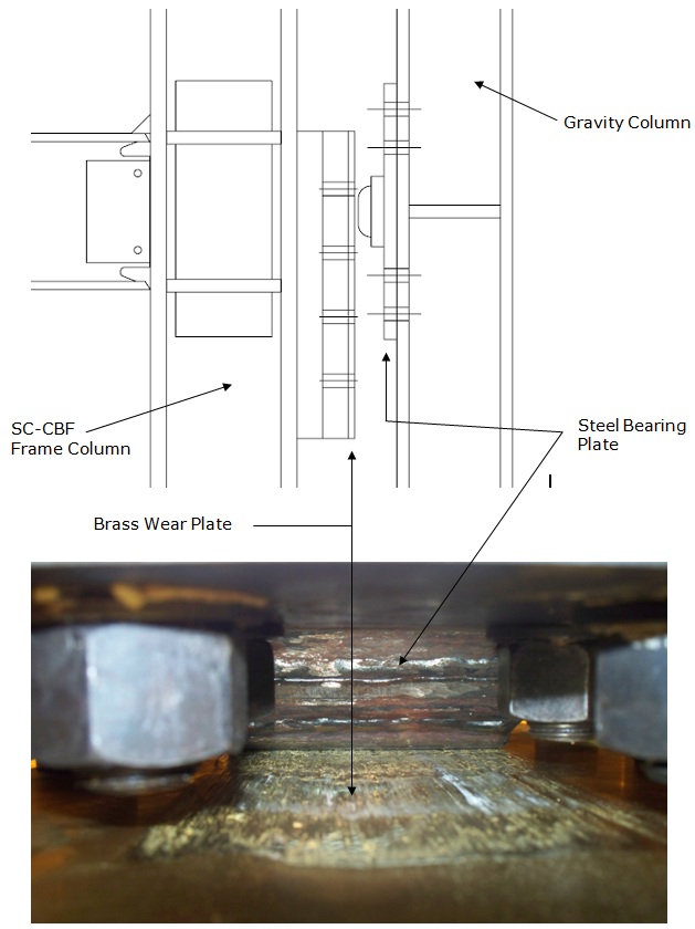
Figure 3: Friction bearing (a) drawing; (b) photograph of bearing from beneath
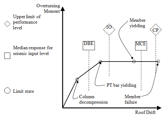
Figure 4 – Schematic of performance-based design criteria
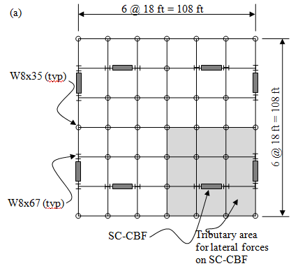
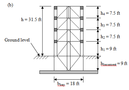
Figure 5 – Prototype Building: (a) floor plan; (b) elevation of SC-CBF
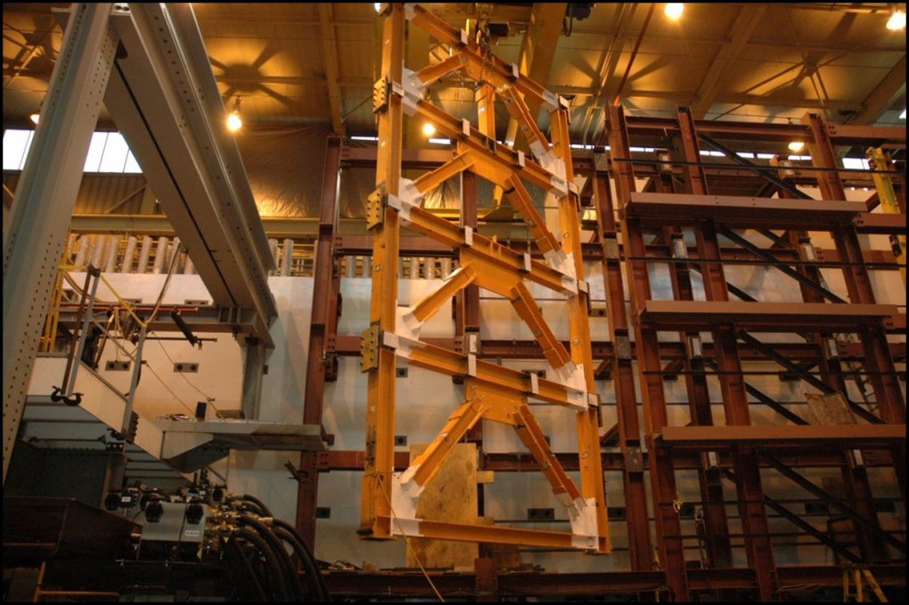
Figure 6 – SCCBF Being Removed
