Testing of NEESR-CR: Post-Tensioned Coupled Shear Wall Systems at Lehigh University Friday, November 08, 2013
November 8, 2013
This NEESR project entitled NEESR-CR: Post-Tensioned Coupled Shear Wall Systems (PIs: Yahya Kurama, University of Notre Dame, and Michael McGinnis, University of Texas at Tyler) is conducting large-scale experiments and accompanying numerical simulations of post-tensioned coupled shear wall structures at the Real-time Multi-directional (RTMD) Earthquake Simulation Facility, the Lehigh NEES Equipment Site. The goal of this NEESR project is to develop a new type of earthquake-resistant reinforced concrete (RC) coupled wall system with significant performance and economic benefits over conventional coupled wall systems. Typical coupling beams in current construction are difficult to construct (they require large amounts of reinforcing steel arranged in complex geometries) and can experience considerable damage under seismic loading. In comparison, the primary reinforcement in the coupling beams of the new system consists of a single unbonded post-tensioning (PT) tendon, greatly simplifying construction. The use of post-tensioning to couple RC shear walls represents a significant innovation and transformation, but one that can be realistically achieved by utilizing the widely-used post-tensioned floor slab construction technology. The deformations in a post-tensioned coupling beam occur primarily in the form of gap opening at the ends, resulting in little damage as the structure displaces laterally during a large earthquake. After the earthquake, the PT tendons provide a restoring force that closes the gaps and pulls the structure back toward its undeformed, plumb position.
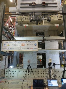
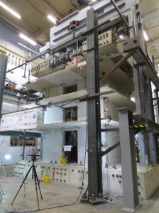
The single major barrier to the use of post-tensioned coupled wall structures in seismic regions is the lack of experimentally-validated design methods, construction procedures, and numerical simulation models. To fill this knowledge gap, large-scale physical laboratory experiments integrated with computer simulations of multi-story coupled wall structures are being conducted. The first specimen, to be tested on November 8, 2013, includes the first three floors, tributary slabs, and the foundations of an 8-story prototype building, representing the most critical regions of the structure. The 3-story test specimen, constructed at 40%-scale, consists of two C-shaped wall piers with a total of 6 coupling beams in between (two beams at each floor level). The reinforcement in each coupling beam includes an unbonded PT tendon near the centroid as well as energy-dissipating mild steel reinforcement near the top and bottom of the cross-section. The energy dissipating mild steel is also deliberately unbonded over a pre-determined length near the beam ends to limit the maximum steel strains and prevent low-cycle fatigue fracture. In addition to the PT steel in the coupling beams, the floor slabs are also reinforced with unbonded PT strands, with a distributed strand pattern in the direction of the beams and a banded pattern in the perpendicular direction.
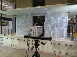
The 8-story prototype building that forms the basis of the test specimen was designed in collaboration with Magnusson Klemencic Associates and Kenneth B. Bondy. The Equivalent Lateral Force Procedure described in ASCE 7 was used in the design, with additional displacement-based performance criteria to achieve the desired performance under the Design Basis and Maximum Considered Earthquake levels. The specimen will be tested under a pseudo-static reversed-cyclic lateral displacement history applied in the direction of the coupling beams. The lateral displacement history will satisfy the validation testing requirements specified by ACI ITG-5.1 (Acceptance Criteria for Special Unbonded Post-Tensioned Precast Structural Walls Based on Validation Testing and Commentary); thus, leading to the classification of the new system as “special” RC shear walls for use in moderate and high seismic regions of the U.S. The loading system consists of a total of 9 servo-controlled hydraulic actuators as follows: 1 actuator to impose lateral displacements on the structure, 2 actuators to control the relative lateral displacement between the two wall piers, 4 actuators to apply an axial load and overturning moment on top of the wall piers, and 2 jacks to apply superimposed gravity loads on the wall piers. The deformations of the laboratory structure will be monitored using multiple three-dimensional digital image correlation sensors, and the resulting near-full-field data will inform the other project areas. Ultimately, this information will lead to the development of validated design procedures for the new system. The project team has also developed detailed analytical (numerical simulation) models of the structure, and the test data will be used to validate these models as well.
This project is a collaborative effort that includes the University of Notre Dame, University of Texas at Tyler, and Lehigh University. The concrete used to construct the test specimen was donated by Essroc Italcementi Group, the PT anchors were donated by Hayes Industries, Ltd., the PT strand was donated by Sumiden Wire Products Corporation (SWPC), and the formwork was donated by A.H. Harris & Sons, Inc. Additional material donations were made by Dayton Superior and Casilio Concrete.
The experiments can be viewed by telepresence at http://tpm.nees.lehigh.edu/portal?section=local_video, where webcams are located and the Real-Time Data Viewer can be used to view data and plots of the response of the building acquired from the test. Results (including videos) from completed tests will also be archived and available below and through the Project Warehouse on NEES.org.


